Welcome to Bob & Eileen's web site. Bob generally blogs here while Eileen blogs over at her site. You can see our photos from here or click the little camera in the upper right corner.

Calendar

November 2024
S M T W T F S
 12
3456789
10111213141516
17181920212223
24252627282930

September 18, 2011

Sensors for the robot project

Filed under: Machining,Robots — Bob @ 3:07 pm

My outdoor robot project is coming along nicely, but so far it has been completely blind. I needed to add some sort of sensors.

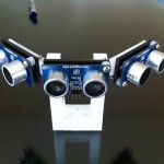
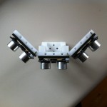
Eventually I’ll have all sorts of sensors, but I decided the first one should help avoid running into things. I opted to use three Parallax Ping))) ultrasonic sensors. I wanted to mount them at different angles, so I’d get a larger view of potential obstacles. This configuration is set up at 45 degree angles, but the design is flexible so I can replace the angled bracket with another, if it turns out this is not sufficient.

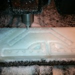
I machined the various parts from 3/8″ delrin (video of some machining operations) then fabricated some mounts for each sensor module from 3mm Sintra (expanded PVC) sheet. Turned out pretty well, I think!

I need to fabricate and program the electronics to drive these three sensors and send messages about object detection, but that will be a topic for another post.

August 28, 2011

It Moves!

Filed under: Electronics,Machining,Robots — Bob @ 3:31 pm

My outdoor robot project has reached the stage where it can move under its own power, without tethering or remote control.

It doesn’t yet have any sensors, so its sort of blind, so I purposefully set it to go slowly around in a circle for 20 seconds or so. Didn’t want to have to chase it!

The next step is to mount some ultrasonic sensors and add some navigation code, and let it wander. Probably need to enable that remote kill switch I was experimenting with…

May 2, 2011

Improved Suspension

Filed under: Machining,Robots — Bob @ 7:35 pm

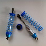
During the construction of my outdoor robot I found that the original RC truck suspension was too soft, not able to really stand up to the added weight of the new structure. I found new, stiffer springs for the shocks, however these new springs were larger than the originals and would not correctly fit.

I needed to create some retainers that would fit the existing shocks but also securely hold the new springs so they could not slip off. I ended up using some blue nylon plastic rod and turned it on the lathe to make retainer rings. In the picture above, you can see these retainers at each end of the spring.

Outdoor Robot Project Update

Filed under: Electronics,Machining,Robots,Uncategorized — Bob @ 7:08 pm

Can’t believe how much time has passed since I’ve posted anything. I really should try to make up for that oversight.

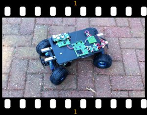
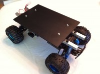
My robot project continues to evolve, the mechanical parts are coming together rather nicely. The picture here shows the most current status, with the chassis, motors, suspension, battery holder and deck are in place. The electronics will be mounted to the deck as soon as I get the boards back from production by BatchPCB.

The boards will be the interface between a Gumstix Overo and the motor controller and sensor boards. I’m using CAN as the communication mechanism. My other post sort of explained how that all works.

My hope is to have the robot up and running around by late June, in time for the Vancouver Mini Maker Faire. The Vancouver Robotics Club will be doing demos all weekend.

July 4, 2010

Wheels go round and round

Filed under: Machining,Robots — Bob @ 8:02 pm

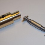
Today marked quite the milestone for my Outdoor Robot project. The last remaining mechanical parts to make for the drive train functional are complete! In the picture here you can see the brass coupler and a steel drive shaft. The gearbox from the RC truck was originally set up to use a “dogbone” drive shaft – a linkage that allows rotation plus slight shifts up and down without stressing the shaft itself. A real “dogbone” shaft has a ball on each end with a pin to fit into the groove of the receptacle socket. Mine were made on my lathe and aren’t quite as nice, but still functional.

The drive shaft is made from 1/4″ steel rod turned down at each end using my Sherline lathe. This was the first time I turned steel on it, and it was surprisingly easy to work with. So far I’d say brass and steel are better materials to work with than aluminum (at least on the lathe). I turned each end down to 0.2″ then proceeded to cut the end to be somewhat ball-shaped. I only needed a couple of these so eyeballing it worked really well. The pin is some brass rod I had, super-glued into place. I liked the idea of using a softer material so it can shear away if necessary to prevent motor or gearbox damage in case of excessive force.

The coupler has a socket at one end (to accept my faux-dogbone drive shaft) and a 6mm hole with set screw to attach to the motor shaft. I turned some brass stock down to 0.6″ then drilled out the center for the motor shaft. Mounting it on my mill gave me a good setup to drill the hole for the set screw and mill out the groove on the socket. A tapped hole in the side for a 8-32 set screw completes the job. Depending on how well this holds up I may end up making a new version out of steel.

Here is another picture of the coupler and drive shaft, showing how the two parts fit together. The last picture shows the parts mounted on the robot itself. This now means the mechanical part of the drive train is complete, and (with some batteries and electronics) the robot will soon be rolling around my yard.

Next Page »
Powered by: WordPress