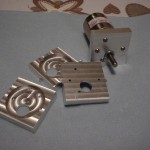
Motor mount, in aluminum
I have been working, ever so slowly, on a larger wheeled robot. My efforts to date have mostly comprised of collecting parts: motors, wheels, gears, a GPS module, various electronics bits, a nifty digital compass, etc. I’ve finally started design and manufacture of various parts to start stitching together everything.
 My first machined part is a bracket to mount the motor (a Lynxmotion model). This picture shows the four brackets I need; one is mounted on a motor, the one in the front-left is finished and the other two need only to have the “tabs” cleaned up.
I designed the part using Inkscape then exported a DXF file and did the machining on my CNC-equipped Sherline (as described in a previous post). You can see the image of the Inkscape design here. This process works quite well for me.
The problem of course is that the design requires “tabs” between the parts in order to be able to hold the whole thing together while machining. I’ve captured a couple of photos here and here to show what it looked like before I cut everything apart.
Next up is the brackets to attach to these mounts. My initial design will take longer to machine though. The idea is to allow each wheel to pivot independently; the bracket is an “L” shape that extends up and over the center of each wheel. It will make more sense when I have some pictures.


